From Shader to Physical Animation - the Voronoi Cellular Zoetrope
Oct 25, 2017 16:10 · 1693 words · 8 minutes read
This is a continuation of Part 1 and Part 2 of the Zeotrope project.
Motivation
This was the final phase of our homework assignment for Design for Digital Fabrication which was to design something algorithmically and laser cut it. Now that the mechanics of the Zoetrope animation were proven out the previous week, it was time to generate something elaborate. I was particularly inspired by John Edmark’s animated bloom sculptures:
After seeing what he made, my goal was to create an animation that:
- loops continuously
- is seamless between frames, allowing the frames to appear as a single image when placed next to each other.
The Animation
I searched around the web for an animation that would fit this criteria and when I came across the chapter on cellular noise in The Book of Shaders, I realized that the Voronoi Algorithm would be ideal.
I couldn’t use an out of the box Voronoi generator in Illustrator or Processing because I needed to:
- render the cells in an arc using radial coordinates so that they could be tiled in a circle
- be able to specify and parameterize the border sizes
- make the animation frames next to each other tilable/seamless
- control how the points are placed and cells are shifted for each animation frame.
The only way to do this would be to have full control of the Voronoi generation.
For a great explaination of the Voronoi algorithm, see the book of shaders. In order to be able to laser cut Voronoi cells, I would need vectors that define where the edges of the voronoi cells lie. Inigo Quilez’ Voronoi Border variation could accomplish this, as it clearly defines the difference between a border and the interior of the cell:
 source: The Book of Shaders
This flavor of the algorithm works by, for each pixel, finding the two nearest Voronoi points, bisecting them, and calculating the distance of the pixel from the plane that is perpendicular to the line that intersects on that bisected point. The pixel’s color is determined by this distance.
source: Inigo Quilez
To make this shader just render borders, I modified it by using the step function to determine if the pixel should appear, and setting that as the alpha:
vec3 c = voronoi(st);

float show = 1. - step(0.1, c.x);

gl_FragColor = vec4(vec3(1.),show);
view all of the code here
As it stood, the cells in the edges used points that extend beyond the edges:
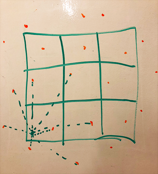
To fix this, in all of the cells at the edges, instead of searching for points that extended past the edges, I used points from cells on the opposite end:
int cols = 3;
int rows = 3;
vec2 getWrappedPoint(vec2 point) {
  int x;
  int y;

  if (point.x < 0.) {
    x = cols - 1;
  }
  else if(point.x >= float(cols)) {
    x = 0;
  }
  else {
    x = int(point.x);
  }

  if (point.y < 0.) {
    y = rows - 1;
  } else if(point.y >= float(rows)) {
    y = 0;
  } else {
    y = int(point.y);
  }

  return vec2(x, y);
}

vec3 voronoi( in vec2 x ) {
  vec2 n = floor(x);
  vec2 f = fract(x);

  // first pass: regular voronoi
  vec2 mg, mr;
  float md = 8.0;
  for (int j= -1; j <= 1; j++) {
    for (int i= -1; i <= 1; i++) {
      vec2 g = vec2(float(i),float(j));
      // convert to wrapped point
      vec2 o = random2(getWrappedPoint(n + g));
      o = 0.5 + 0.5*sin( u_time + 6.2831*o );

      // rest of code left out for brevity purposes.  Click link below to see full examplele
    }
  }
  // rest of code left out for brevity purposes.  Click link below to see full examplele
}
view all of the code here.
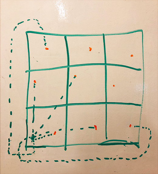
This caused the edge cells to wrap around to the cells on the opposite end, letting the frames be tilable:
Projecting the Animation onto a Circle
For this animation to be projected onto a circle for the Zoetrope, it had to:
- Contain 33 frames, and loop at the end of the sequence.
- Have each frame be converted into an arc, and make these arcs tilable.
- Rotate each arc frame around a circle
I used Processing to accomplish this, as I discovered it’s incredibly easy to work with shaders and render frames using a buffer.
To make the animation 33 frames long, in Processing, the u_time uniform was set to be frame / 33:
shader.set("u_time", frame / 33.0);
In the shader, the animation was set to repeat every sin(u_time * 2 * PI):
o = 0.5 + 0.5*sin( u_time * 2 * PI + 6.2831*o );
To render the frame as an arc with a transparent background, the x and y were converted into radial coordinates, and everything outside of the 2 * PI /33 size arc had an alpha of 0, making those areas transparent:
int frames = 33;
float totalTheta = 2. * PI / float(frames);
float minTheta = -totalTheta / 2.;

// origin is at the middle top of the screen
vec2 origin = vec2(0.5, 1.);

vec2 getRadialCoords(vec2 point) {
  float y = length(point - origin);
  float xMagnitude = point.x - origin.x;
  float theta = sin(xMagnitude / y);
  return vec2((theta - minTheta) / totalTheta, y);
}

// rest of code left out for brevity purposes

void main() {
  vec2 st = gl_FragCoord.xy/u_resolution.xy;
  st.x *= u_resolution.x/u_resolution.y;
  st = getRadialCoords(st);
  vec3 color = vec3(0.);

  float show = (1. - step(1., st.y));
  show *= step(0., st.x) * (1.-step(1., st.x));

  // Scale
  st *= vec2(2., 8.);// cells;
  vec3 c = voronoi(st);

  show *= 1.-step(0.09, c.x);

  gl_FragColor = vec4(vec3(1.),show);
}
To project this onto a circle in Processing, each frame was rendered into a PGraphics buffer,
then the scene was rotated, scaled, and the buffer was rendered as an image in the proper size and rotation:
PShader frag;

int frames = 33;
float frameTheta = 2. * PI / frames;

int h = 300;
int w = 300;
float base = 2 * tan(frameTheta / 2.)* h;
int renderSize = ceil(base);

float sliceAspect = sin(1. / frames * 0.5 * 2 * PI) * 2.;
int frameWidth = ceil(h * sliceAspect);

void settings() {
  size(w, h, P2D);
}

PGraphics pg;

void setup() {
  frag = loadShader("colorfrag.GLSL", "colorvert.GLSL");
  frag.set("u_resolution", float(frameWidth), float(h));
  frag.set("u_cells", float(3), float(14));
  frag.set("u_bordersize", 0.1);
  frag.set("u_miny", 0.1);

  background(255);
}

int frame = 0;
void draw() {
  // circle complete, stop animating.
  if (frame > frames) noLoop();

  noStroke();
  frag.set("u_time", frame * 1.0 / frames);
  // create buffer
  pg = createGraphics(frameWidth, h, P2D);
  pg.beginDraw();
  // render the shader in the buffer
  pg.filter(frag);
  pg.endDraw();

  translate(w/2, h/2);
  scale(0.5);

  rotate(lerp(0, -2. * PI, float(frame) / frames));

  // after rotation, move frame to the middle
  translate(-frameWidth/2, 0);
  image(pg, 0,0 );
  frame++;
}
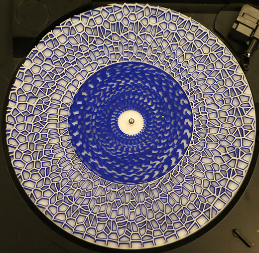
As the voronoi approached the center of the circle, the borders become narrower and more skewed - this would be nearly impossible to cut. To improve this, within a specified radius, the animation was changed to be a different voronoi animation from the book of shaders, meatballs:
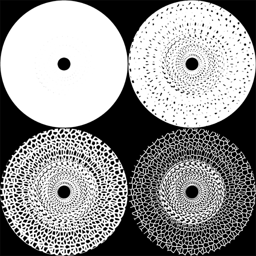
With the animation created, I wanted to laser cut multiple layers of it, each with a slightly larger border, enabling the physical layers to have different colors and stack on top of each other, creating a sort
of 3D/depth effect. To generate these layers in processing, I parameterized the shader to be able to specify the border size and the color it renders.
For each layer, the animation was projected around the circle with these parameters set layer by layer:
view the code for this here
Preparing for Laser Cutting
Converting these layers into vectors that could be laser cut was pretty straightforward. First, I modified the processing script to render each layer as a separate image with resolution 2000x2000, and white for where the borders would be:
To convert a layer into a vector for laser cutting, in Adobe Illustrator, I:
- Converted the generated image for layer to a vector by used Image Trace.
- selected all of the black fill vectors and deleted them.
- scaled the layer to its real size of 30 cm (or 11.81”).
- converted all the vectors to a red stroke with 0.1 size, so that the laser cutter would recognize it for cutting.
 Layer 2 prepared for laser cutting in Illustrator
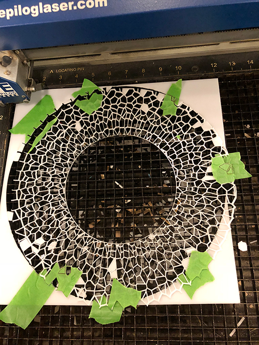
Laser Cutting
The laser cutter was able to easily read these vectors and cut the layers:
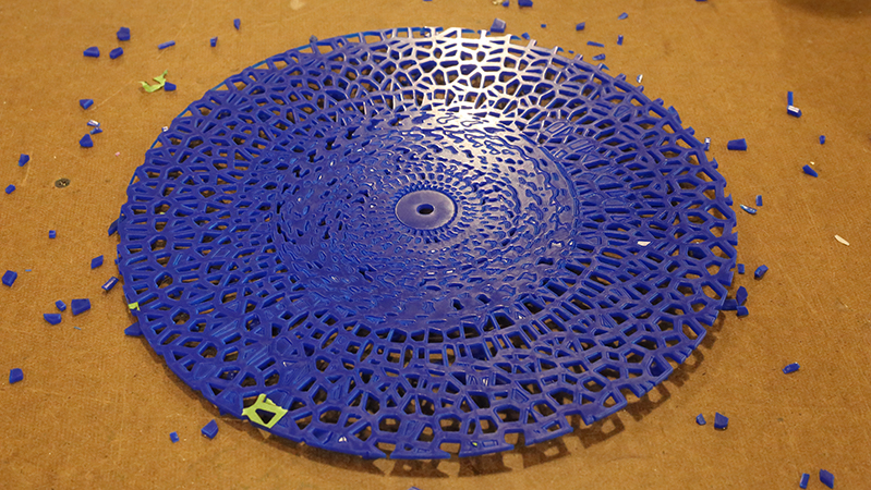
Layer 1 on a blue background
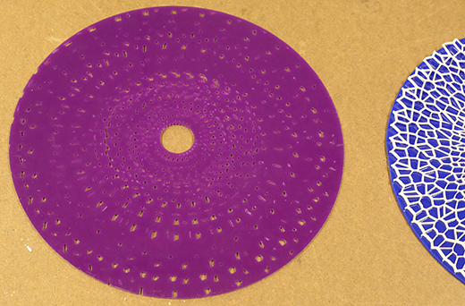
Layer 3 (did not end up being used)
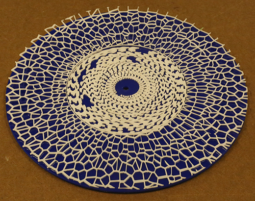
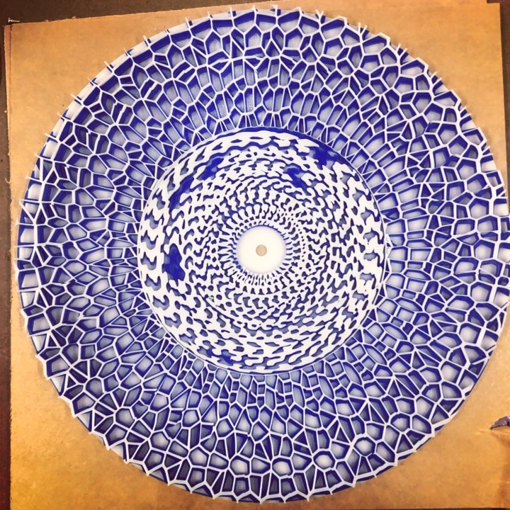
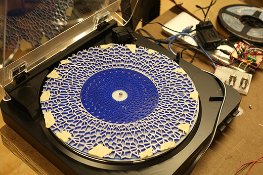
I tried stacking all the layers as originally intended on top of each other, but the blue on the bottom was barely visible under the purple. I found the best combination was white top layer, blue under it, and white background:
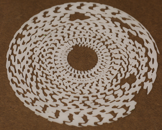
The middle part, the meatball variation, ended up with a few gaps where the animation was not attached to the rest of the disc. I had intended to attach these back on, but these pieces fell through the cracks when laser cutting. I left it off the main zoetrope animation:
 I used acrylic glue to attach the top two layers to each other:
Filming the Zoetrope
When it came time to film this animation, I wanted to do it without needing the rgb led flashers from my previous experiments because the camera does not properly capture the strobe effects. I realized then why in Retchy’s post on Zeotropes he recommended using 33 frames of animation:
At 45 rpm, or 0.75 rotations per second, with 33 frames, dividing the frames by rps gives us 24.75 frames appearing each second. This lines up closely with the camera’s standard 24 fps. I filmed this using the Canon Mark III generously provided by ITP; with a high shutter speed (1⁄4000), this created the wonderful effect of a physical, seamless animation:
Conclusions / Future Work
I’m incredibly pleased with the results of this experiment as it surpassed my expectations. I’d like to explore creating some more animations such as one that depicts entering an infinite spiral. I also want to figure out a proper setup for the flashing light and interacting with its speed. I hope others can learn from this, use it as a resource, and be inispired to create something better.