Generating Zoetrope Animations
Oct 12, 2017 13:25 · 1624 words · 8 minutes read
This is a continuation of Part 1 of the Zeotrope project for my Design for Digital Fabrication class. The final phase can be seen in Part 3
The next step of the project was to prototype the mechanics of the animation. The main questions were:
- How many frames of animation are optimal?
- What should the rotation speed be?
- At what rate should the lights flash?
The Rotation Mechanism - a Turntable
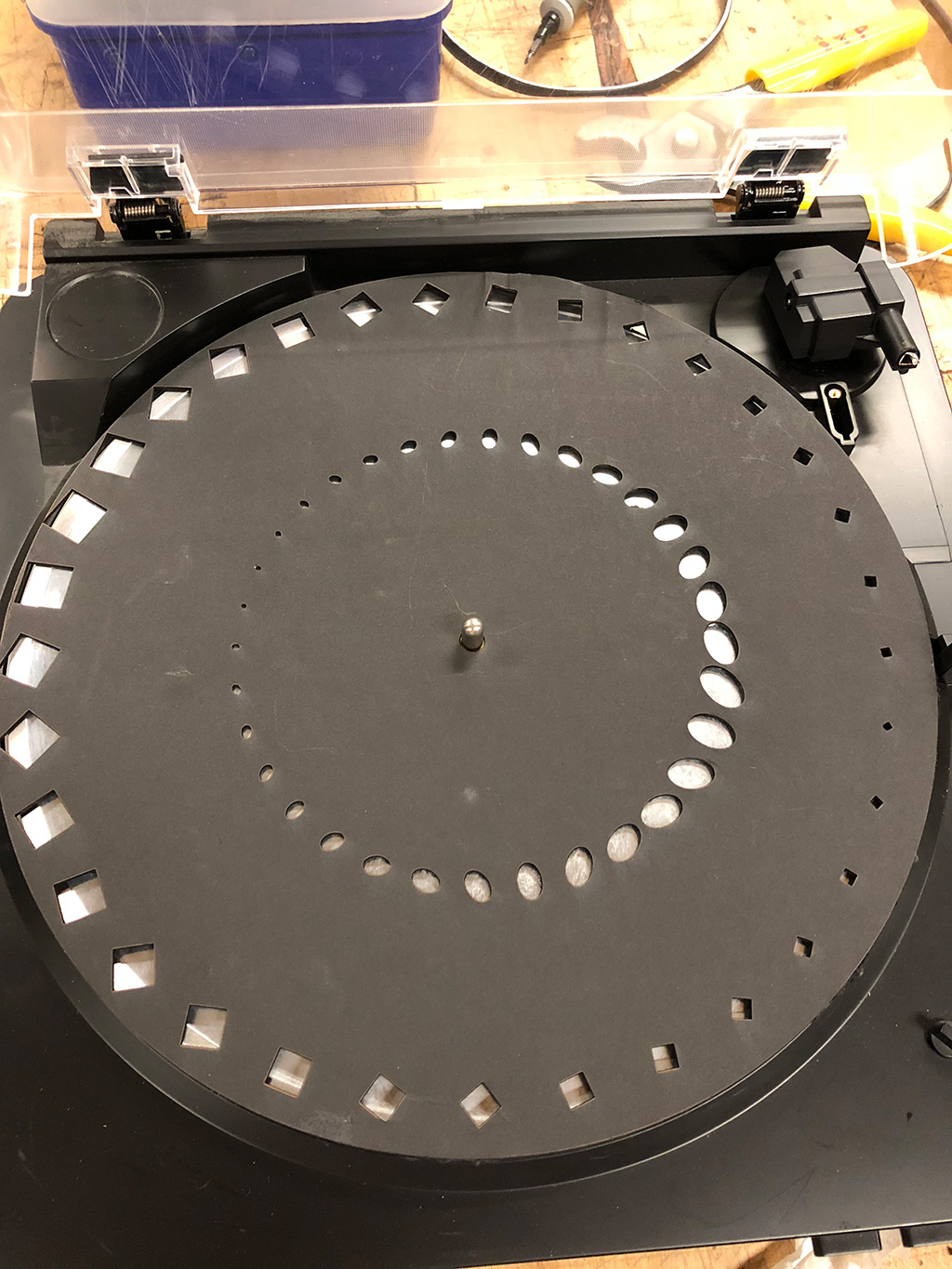
There were many examples of Zoetropes on the web - the majority of them used a turntable to rotate the animation.
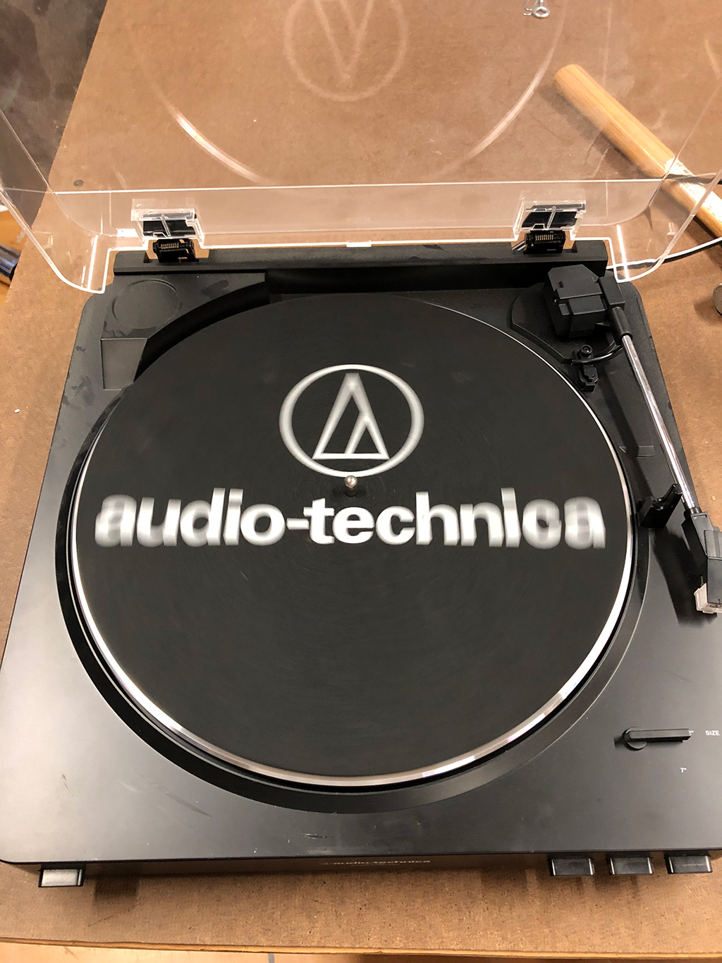
I figured this would be the quickest and most affordable way for me to get something up and running. I found and purchased a $30
used Audio Technica one on Facebook Marketplace, for which the owner said that the sound didn’t work. This would be perfect
as all I needed was a consistent rotation speed. I met the owner at a coffeeshop, purchased it, and brought it back to the ITP shop:
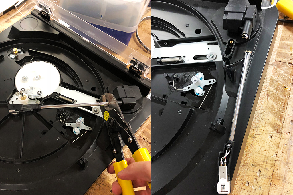
As the turntable was automatic, it had an annoying feature where when it would start up, it would force the tonearm onto the rotating plate. When I’d push the tonearm back onto the stand, the rotation would stop. The tonearm could not be on the plate when an animation is running. To solve this I removed the bar that was pushing the tonearm up and cut off the tonearm with shears:
Generating the Animation in Processing
For the animation, I followed the advice on Retchy’s blog on Zoetropes to use 33 divisions of a 30cm circle. I couldn’t figure out if the rpm should be 33.5 or 45 but went with 33.5 rpm for these experiments.
To algorithmically generate the frames I went with Processing, as it would let me easily tweak a parameter to change things such as the disc and frame size, and would also allow me to see what the disc would look like when rotating at a desired rpm.
I wrote a simple sketch that draws 33 evenly sized arcs in a circle, starting from the bottom center and rotating counter clockwise, which would render the frames in the order they appear. The key here is that the whole scene is rotated before drawing a frame - this would allow an animation frame to be drawn without having to worry about rotating all the elements, as the frame itself is rotated.
int w = 800;
int h = 800;

final int FRAMES = 33;
final int DIAMETER = w;
final float ARC_ANGLE = 1.0 / FRAMES * 2 * PI;

void settings() {
  size(w, h);
}

void setup() {
  noFill();
  // draw the outer circle
  ellipse(w/2, h/2, w, h);
  for(int i = 0; i < FRAMES; i++) {
    drawArcForFrame(i);
  }
}

void drawArcForFrame(int frame) {
  pushMatrix();
  noFill();
  translate(w / 2,  h /2);
  // rotate the frame before drawing it
  rotate(-ARC_ANGLE * frame);
  drawFrameBorder();
  popMatrix();
}

void drawFrameBorder() {
  arc(0, 0, DIAMETER, DIAMETER, PI/2 - ARC_ANGLE / 2.0, PI/2 + ARC_ANGLE / 2.0, PIE);
}

With the frames worked out, it was time to draw an animation frame in each arc. This is easier now as instead of drawing an arc, a frame of the animation can be drawn, but with a translation and rotation already applied that would draw the frame in the correct orientation and position. I animated a square that starts at the border and shrinks as it rotates towards the center. I also drew a circle in the center of the circle which would allow the 7mm diameter spindle of the turntable to fit in:
int w = 800;
int h = 800;

final int FRAMES = 33;
final float ARC_ANGLE = 1.0 / FRAMES * 2 * PI;

void settings() {
  size(w, h);
}

float sizeInCm = 30;
float cmScale = w / 30;
float centerHoleDiameterMm = 0.7;
float centerHoleSize = centerHoleDiameterMm * sizeInCm;

void setup() {
  noFill();
  // draw the outer circle
  ellipse(w/2, h/2, w, h);
  // draw the circle for the hole in the center
  ellipse(w/2, h/2, centerHoleSize, centerHoleSize);
  for(int i = 0; i < FRAMES; i++) {
    animateFrame(i);
  }
}

void animateFrame(int frame) {
  pushMatrix();
  noFill();
  translate(w / 2,  h /2);
  // rotate the frame before drawing it
  rotate(-ARC_ANGLE * frame);
  drawRotatingSquare(frame);
  popMatrix();
}

float rotationSpeed = PI / 7;
final int DIAMETER = w;
final int FRAME_HEIGHT = DIAMETER / 2;

void drawRotatingSquare(int frame){
  float percentage = frame * 1.0 / FRAMES;

  pushMatrix();
  float size = lerp(40, 1, percentage);
  translate(size / 2 + lerp(-20, 0, percentage), size / 2 + lerp(FRAME_HEIGHT - 45, 0, percentage));
  rotate(PI / 7 * frame);
  rect(-size/2, -size/2, size, size);
  popMatrix();
}

I also wanted to test an animation that looped, so I created one with an ellipse and a square that rotate, shrink and expand in a cycle. This is the updated animateFrame method:
void animateFrame(int frame) {
  pushMatrix();
  noFill();
  translate(w / 2,  h /2);
  rotate(-ARC_ANGLE * frame);
  drawRotatingSquare(frame);
  drawRotatingEllipse(frame);
  popMatrix();
}

final int DIAMETER = w;
final int FRAME_HEIGHT = DIAMETER / 2;
int HALF_FRAMES = FRAMES / 2;

float getPercentage(int frame) {
  //int frameInHalf = frame % HALF_FRAMES;
  float percentage;
  if (frame < HALF_FRAMES)
    percentage = frame * 1.0 / HALF_FRAMES;
  else
    percentage = 1 - (frame - HALF_FRAMES) * 1.0 / HALF_FRAMES;

  return percentage;
}

void drawRotatingEllipse(int frame) {
  pushMatrix();
  float percentage = getPercentage(frame);
  float size = lerp(3, 35, percentage);
  translate(lerp(-5, 7, percentage), size / 2 + 200);
  rotate(PI/5 * frame);
  ellipse(0, 0, size * 0.8, size * 1.2);
  popMatrix();
}

float rotationSpeed = PI / 7;

void drawRotatingSquare(int frame){
  float percentage = getPercentage(frame);

  pushMatrix();
  float size = lerp(40, 5, percentage);
  translate(size / 2 + lerp(-20, 0, percentage), size / 2 + FRAME_HEIGHT - 45);
  rotate(PI / 7 * frame);
  rect(-size/2, -size/2, size, size);
  popMatrix();
}

Protoyping the Strobing with SVG
With the animation generated, the rotation on the turntable can be simulated by saving the Processing output as svg and then modifying the svg to have a rotating animateTransform.
The modified processing script that saves the output to svg:
import processing.svg.*;

int w = 800;
int h = 800;

void settings() {
  size(w, h);
}

void setup() {
  beginRecord(SVG, "zoetrope.svg");
  noFill();
  // draw the outer circle
  ellipse(w/2, h/2, w, h);
  for(int i = 0; i < FRAMES; i++) {
    animateFrame(i);
  }
   endRecord();
}
This svg is then edited in a text editor to add the rotating animateTransform.
At 33.5 RPM, the rotation is calculated to occur every 1.79s by dividing 60s by 33.5 rotations.
This 360 degree rotation animation is applied to the svg at the middle of the circle (400, 400):
<svg width="800" height="800">
  <g>
   <animateTransform attributeName="transform"
                            attributeType="XML"
                            type="rotate"
                            from="0 400 400"
                            to="360 400 400"
                            dur="1.79104s"
                            repeatCount="indefinite"/>
    <g style="stroke-linecap:round;">
      <circle r="400" style="fill:none;" cx="400" cy="400"/>
    </g>
    <g style="stroke-linecap:round;"><circle r="10.5" style="fill:none;" cx="400" cy="400"
      />
    <rect x="-20" y="-20" transform="translate(400,775)" width="40" style="fill:none;" height="40"/>
    <!--Rest of svg left out for brevity of example-->
  </g>
</svg>
You can view the source of this svg by downloading it:

To calculate the strobing rate, we need to know the frame duration. This is done by dividing the seconds per rotation by the frames, 1.79s / 33 which comes out to 0.054s per frame. This strobing can be simulated by adding an animation to the svg that changes the opacity from 0 to 1 at a desired rate. After experimenting with various on/off percentages in the svg animation, 20% on and 80% off turned out to produce the most crisp result:
<svg width="800" height="800">
  <g>
   <animateTransform attributeName="transform"
                            attributeType="XML"
                            type="rotate"
                            from="0 400 400"
                            to="360 400 400"
                            dur="1.79104s"
                            repeatCount="indefinite"/>
   <animate id="animation1"
     attributeName="opacity"
     from="1" to="1" dur="0.01085481682s"
     begin="0s;animation2.end" />
    <animate id="animation2"
     attributeName="opacity"
     from="0" to="0" dur="0.0434192673s"
     begin="animation1.end" />
    <g style="stroke-linecap:round;">
      <circle r="400" style="fill:none;" cx="400" cy="400"/>
    </g>
    <g style="stroke-linecap:round;"><circle r="10.5" style="fill:none;" cx="400" cy="400"
      />
     <rect x="-20" y="-20" transform="translate(400,775)" width="40" style="fill:none;" height="40"/>
    <!--Rest of svg left out for brevity of example-->
  </g>
</svg>
WARNING: Do not click to view the below animation if you have epilepsy as it strobes rapidly
View the Strobing Simulation
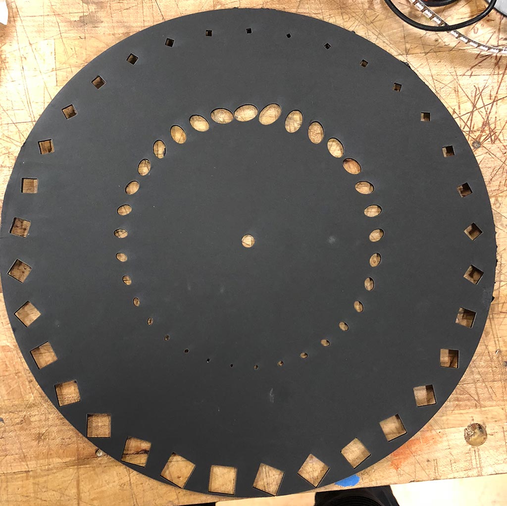
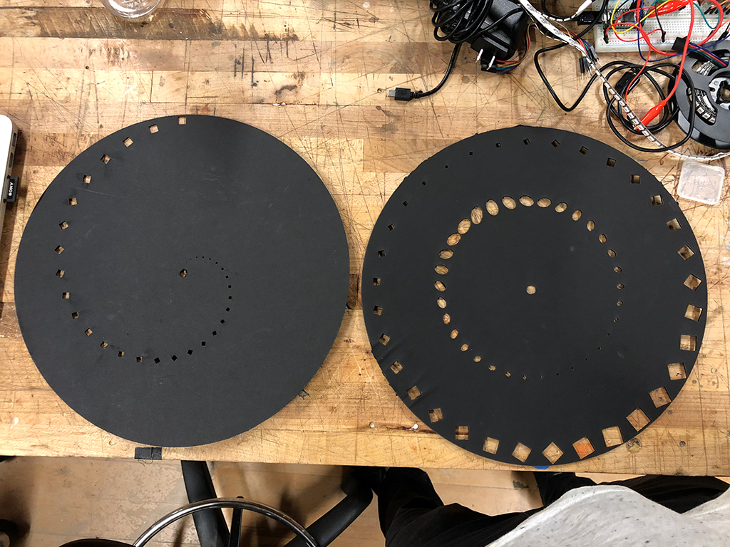
Laser Cutting
These svgs were easily importable into Illustrator, from which I laser cut some matte board I had lying around.
The Strobing Hardware
To build the strobing mechanism, I used a basic analog rgb led strip ($10 on amazon), Arduino Uno, and prototyping shield I had lying around from another project. This shield was already setup as instructed in Adafruit’s guide to rgb leds to control the strip. I connected a potentiometer to be able to adjust the strobing rate. Both the Arduino and LEDs were powered directly by the same 12V power supply by using a barrel jack splitter.
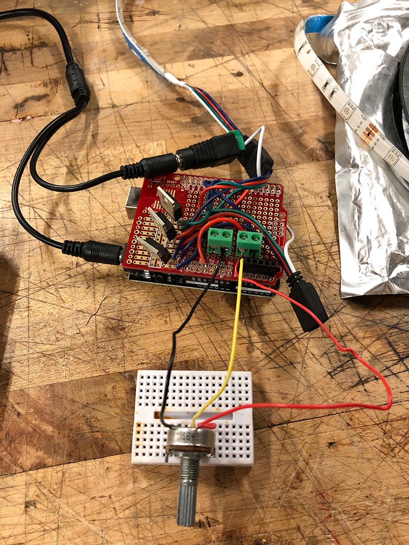
The code is below. It flashes the LEDS on and off based on an interval controlled by the potentiometer. The lights are on for 20% of the interval:
#define LOWER_READ 143
#define UPPER_READ 940

#define INTERVAL_PIN A0
#define REDPIN 5
#define GREENPIN 6
#define BLUEPIN 9

#define ON_PERCENTAGE .2

long lastIntervalStart;
bool on;

void setup() {
  Serial.begin(9600);
  //Serial.println(frameDuration);
  pinMode(INTERVAL_PIN, INPUT);
  pinMode(REDPIN, OUTPUT);
  pinMode(BLUEPIN, OUTPUT);
  pinMode(GREENPIN, OUTPUT);
  lastIntervalStart = millis();
  on = false;

  setColor(255, 255, 255);
}

void setColor(int r, int g, int b) {
  analogWrite(REDPIN, r);
  analogWrite(BLUEPIN, b);
  analogWrite(GREENPIN, g);
}

void loop() {
  float intervalDuration = constrain(map(analogRead(INTERVAL_PIN), LOWER_READ, UPPER_READ, 0.0, 200.0), 0, 200.0);
  float onDuration = intervalDuration * ON_PERCENTAGE;
  float intervalElapsedTime = millis() - lastIntervalStart;

  if (on && intervalElapsedTime > onDuration) {
    on = false;
    setColor(0, 0, 0);
  }

  if (intervalElapsedTime > intervalDuration) {
    lastIntervalStart = millis();
    Serial.println(intervalDuration);
    on = true;
    setColor(255, 255, 255);
  }
}
The Final Result
By fine tuning the strobing interval with the potentiemeter, I could create crisp animations: